
Options for Creating Objects
Introduction
Have a clear strategy for the way in which objects will be created in a design visualisation. There are a number of ways of creating the three main elements of a landscape scene, surfaces, edges and objects, each one demending an understanding of the creation methods and tools at hand
This section describes the main basic creation methods before you would use MAX / VIZ's powerful modifying and sub-object editing functionality to produce a polished 3D landscape
The main options for initially creating objects are as follows:
AutoCAD 2D
Standard Primitives
Shapes
Compound Objects
AEC Extended Objects
Most design visualisations start their life as an AutoCAD design production drawing. However, design visualisation can start at a conceptual design stage using context data from AutoCAD and using MAX / VIZ for spacial analysis, massing studies and diurnal analysis for example
Download Sample Data
kf201_files.zip (209kb)
module_2_maps.zip (5.9mb)
AutoCAD 2D
- Using AutoCAD 2D data is covered in a later tutorial. For this stage in Key Fundamentals look at an example of AutoCAD drawing data that has been imported into MAX / VIZ
- Open kf201_01.max. This contains 2D lines imported straight from AutoCAD
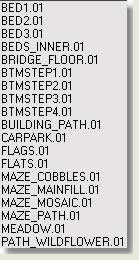
- Select by Name dialog Notice that all the objects have been named automatically when the data was imported. These names come from the layer names in AutoCAD
- Navigate around the scene and objects in the scene to get a feel for the project. This is the project that is going to be 'worked up' into a 3D landscape by Key Fundamentals
Pros
- All surface boundaries and edge lines can be brought into MAX / VIZ without having to redraw
- AutoCAD is very accurate
- Objects can be placed accurately on x,y
Cons
- Objects from AutoCAD are not parametric and need further modification in MAX / VIZ
- Any mistakes or changes need further import from AutoCAD
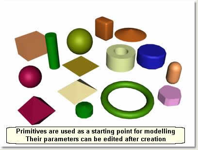
Primitives
'Primitives' means a 'starting point' or geometry (geometry is '3' dimensional in MAX / VIZ) that is used most often to start the modelling process. A Standard Primitive cylinder, for example, would be used to start the process of creating a lamp post. MAX / VIZ provides a host of Standard Primitives and Extended (more) Primitives accessed from the Create Panel. Below is an explanation of how to create Primitives in a scene and change settings for the objects 'parametrically' (parameters can be changed after creation)
- File > Reset
- Create Panel > Geometry > Standard Primitives > Box. Notice that when a command button is active it turns orange
![]()
NOTE: Always note when a command button is active. A command must be completed or stopped before going to another command
- In the Perspective Viewport the cursor changes to a bold cross. Left click and drag the area for the bottom of the box
- Take your finger off the left button and move the cursor up to define the height of the box
- When the height is about right left click to finish creating the box. The cursor stays as a bold cross telling you you can change the parameters of the box on the rollout or indeed create another box
- Whilst still in the command (button is orange) use the Length, Width and Height spinners under Parameters rollout to alter these settings, either typing the value in the box or using the spinners
- Whilst still in the command turn on Wireframe display mode and alter the number of segments using the spinners for segments
- When happy with the result right click in the viewport to stop the comand
NOTE: Instead of right clicking to stop the command you can carry on creating box after box by simply repeating the process - before right clicking to end the command
TIP: In practice do not bother too much about the parameters during creation. These are most effectively changed after creation using the Modify Panel (covered later)
- Practice creating Standard Primitives and also Extended Primitives (next on the dropdown list) and note that the creation methods differ slightly depending on the object used. Just experiment
Pros
- Good for use in creation of 'standalone' objects such as lamp posts, roofs, simple trees, housing mass objects etc
- Parameters can be re-visited eg to alter segment numbers to create smoother bend modification for example
Cons
- Limited use for the general infrastructue of a landscape project (surfaces and edges) - most of this data comes from AutoCAD
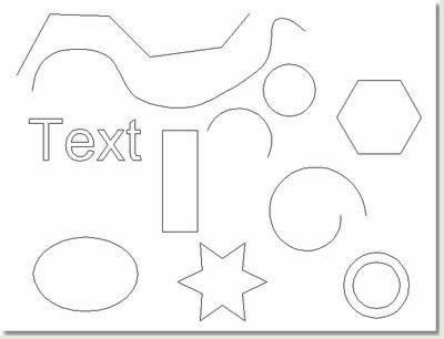
Shapes
Shapes are mainly 2D objects (apart from a Helix and Line which can travel along the Z axis on creation) that, like Primitives, are used to start the modelling process. Again, they are parametrical allowing you to re-visit the object and change parameters such as the radius of a circle after it has been created
- File > Reset Make the Top Viewport active and maximise it
- Create Panel > Shapes > Splines > Line
- Before drawing a line go to the Creation Method rollout and look at the options for creating a line. Spline vertices can be corner, bezier, bezier corner or smooth. Alter the radio buttons to Corner Initial Type and Corner Drag Type
- In the Top Viewport draw a line by left clicking where you want the vertices placed
- Right click to finish drawing that particular line
- Alter the Initial Type and Drag Type and draw another line. Note that this creates another line with different properties
- Right click after finishing a line command (right click) to stop the command (button turns grey)
- Practice creating shapes and experiment with the different methods of creation
Pros
- Shapes are mainly parametrical and can be used as part of a modification 'stack' explained later
- AutoCAD text is imported as a Shape Text Object
- Shapes are used in the Loft compound object, Bevel Profile modifier and Sweep modifier. The parametrical functionality can be passed down to these objects
Cons
- Like Standard Primitives, shapes are mainly used for creating objects and have limited use in the creation of surfaces and edges (apart from lofts, bevel profile and sweep)
Compound Objects
Compound means created from more than one object. A Terrain Compound Object, for example is created from a number of separate splines (contours usually) and a Loft Compound Object is created from a Path and a Shape which is 'lofted' along the Path. In this tutorial you create five commonly used comound objects in the creation of 3D landscapes:
Boolean
ShapeMerge
Terrain
Scatter
Loft
Boolean
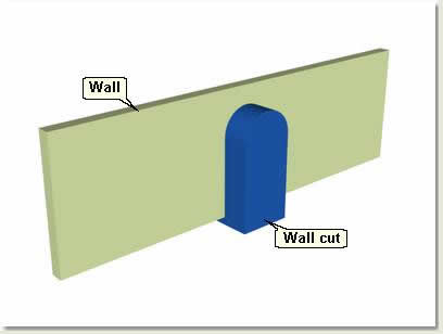
Use Boolean Compound Objects to knock designed shaped holes in walls for example
- Open kf201_02.max. This contains a simple wall called Wall created from a Box Standard Primitive and an object called Wall cut that has been created from a Line and Arc Shape that has been extruded (explained later)
- Select Wall
- Create Panel > Geometry > Compound Objects > Boolean
- On The Parameters rollout notice that under Operands Group Wall has been added as Operand A. Operands are the single objects that make up a compound object
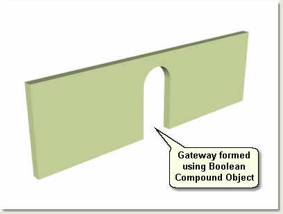
- Press Pick Operand B In the viewport select Wall cut The Boolean Compound Object is created giving you a number of options on the Operation group menu
- Operation Group menu Choose Subtraction (A-B) ie subtract the wall cut from the wall. The wall shape is neatly cut from the wall as shown below
- Experiment with the other options. These are self explanitory
TIP: When finished implementing a Boolean Compound Object turn the object to an editable mesh to save on system resources (this is covered later). Otherwise MAX / VIZ uses processor power and memory to re-create the object each time the scene is opened
ShapeMerge
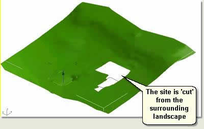
Use the ShapeMerge Compound Object to cut landforms and create new surfaces that respect the original landform. In this way 2D closed boundaries that delineate paths, roads, car parks, planting beds, fairways and greens etc can be 'merged' with accurate design landform (groundmodel mesh) to create new surfaces. The new 3D design surfaces can then be transformed to improve the edge details and have landscape materials assigned to them to look real. Creating accurate 3D surfaces is the first step to producing good 3D landscape scenes
NOTE: The landform mesh in this instance needs to be accurate and include design detail with integrity for each surface as you are using it to create the final surface detail. If the landform mesh is not accurate, then other methods of creating design surfaces must be employed. These are explored in 'Infrastructure and Landscape Modelling'
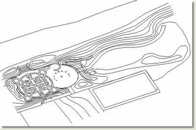
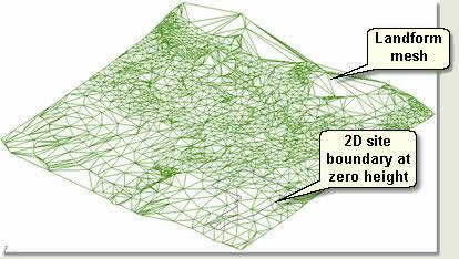
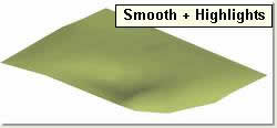
- Open kf201_03.max. This scene contains a 3D landform mesh and a 2D boundary delineating the boundary of a quarry site
- Turn to Smooth + Highlights display mode and select Terrain01
- Create Panel > Geometry > Compound Objects > ShapeMerge > Pick Operand rollout > Pick Shape
- Use Select by Name dialog to pick SITE_BOUNDARY.01 This is a 2D boundary line delineating the boundary of a quarry site
- Operation > check Cookie Cutter The site is 'cut' from the surronding landform
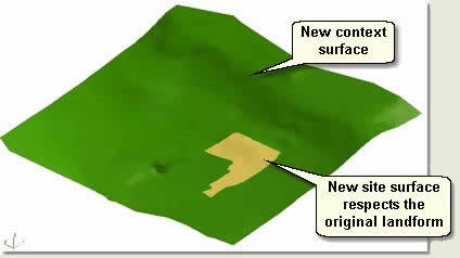
You are now going to copy the ShapeMerge object you have just created and invert the operation on one ShapeMerge object to create two new surfaces: one a site surface, the other a context landform
- Right click to stop the ShapeMerge command (Pick Shape button turns grey). Make sure Terrain01 is still selected
- Edit Menu > Clone > check Copy leaving the default name Terrain02 > OK
- Make sure Terrain 02 is still selected
- Modify Panel > Operation rollout > check Invert. This inverts the cookie cutter operation, keeping the site surface and deleting the context landform
TIP: If the surface seems to have been 'filled in', this is just because the new site surface is the same colour as the context landform. Simply go to the colour swatch by the name Terrain02 and change the colour
Once the operation of creating new surfaces has been completed your attention should turn to helping system resources by turning each surface into an editable mesh thus:
- Select Terrain01 and Terrain02
- Right click quad menu > Transform menu > Convert To > Convert to Editable Mesh
- Rename the new surfaces Site surface and Context surface
Terrain
The Terrain Compound Object is an invaluable asset for landscape and urban design work, not least because the landscape is comprised mostly of surfaces, with edges and objects being secondary in terms of the creation process. It is another way of creating surfaces in MAX/VIZ from 2D lines and 3D polylines created in AutoCAD (usually contours at different heights) or indeed in MAX/VIZ
- Open kf201_04.max. This scene has been set up with the correct environments settings and zoom and does not contain any objects
- Create Panel > Shapes > Line
- Creation Method rollout Change the Initial Type to Smooth and Drag Type to Smooth
- Draw 5 or 6 contour lines at zero height then use Select and Move Transform Type In floater to move each contour to 1, 2, 3, 4 metres high in sequence
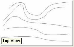
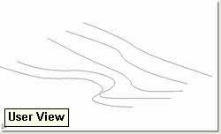
- Select all the lines by windowing around them in the viewport. Maximise the User Viewport and view the lines as above
- Create Panel > Geometry > Compound Objects > Terrain. The lines are converted to a Terrain Compound Object
- In the Select by Name dialog note that the line selected last is now called Terrain01 and the remaining lines still exist. These remaining lines can be deleted at any time
- Select (using the Select by Name dialog) all objects apart from Terrain 01 and delete them for the purposes of this tutorial
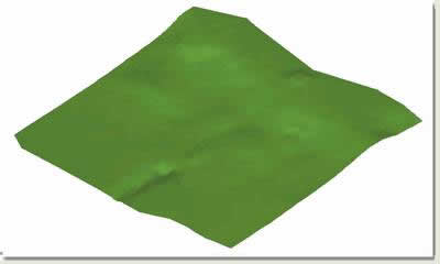
- Change the terrain colour to green then experiment, turning the display mode to Wireframe and Smooth + Highlights to view the terrain form
- Open kf201_05.max. This scene contains a much larger set of contours from AutoCAD These have been converted to a single object as part of the import process
- Select CONTOURS and convert to a Terrain Compound Object as previous. Remember to right click after creating the terrain to stop the command
Terrain Object Options
- Select the terrain Terrain01
- Modify Panel > Pick Operand rollout Notice you can pick further lines to add these to the terrain
- Parameters rollout Notice you can pick Operands (contours) individually and delete them from the terrain. This terrain, however has been created from one editable spline object
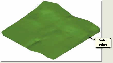
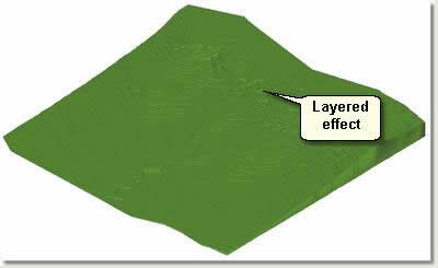
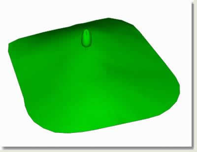
- Parameters rollout > Form > check Graded Solid This creates a solid effect as below
- Parameters rollout > Form > check Layered Solid
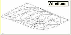
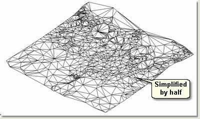
- Change the Form back to Graded Surface and the display to Wireframe mode
- Simplification rollout > Horizontal > check Use 0.5 of Points
- Simplification rollout > Horizontal > check Interpolate Points * 2
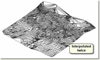
- Return the settings to No Simplification
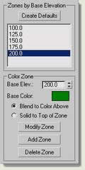
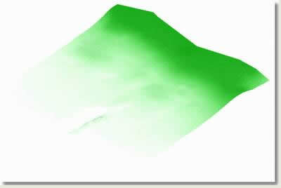
- Color by Elevation rollout You will create a colour by elevation graphic for the terrain. This effects vertex colours and is usefull for presenting terrain height information visually
- Notice that the Maximum Elevation is 192 and the Minimum Elevation is 100
- Color Zone Type 100 in the value box
- Change the Base Color whiteness to just above white
- Press Add Zone This means that the terrain above this level will now be this colour
NOTE: The change in colour is only evident in an output render time and not in the viewport
- Color Zone Type 125 in the value box
- Change the Base Color whiteness to about one quarter above white
- Press Add Zone This means that the terrain above this level will now render as this new colour
- Repeat untill you have added five zones thus
- Quick Render. View the results
- Experiment by changing colours and then pressing Modify to get many different effects
- Alter the heights globally by changing the Reference Elevation value. This alters the start height of the colours
Scatter
The Scatter Compound Object randomly scatters clones of one object over the surface of another. For landscape work this is useful to scatter trees over a terrain for example
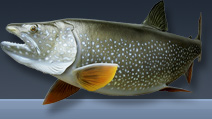
- Open kf201_06.max. This scene contains a terrain and a simple tree. You are going to scatter the tree over the surface of the terrain and explore options for the Scatter Compound Object
- Select Simple tree
- Create Panel > Geometry > Compound Objects > Scatter
- Pick Distribution Object rollout > Pick Distribution Object. Check Instance. Select Terrain in the viewport. The Tree is positioned on a new terrain and is an operand of a Scatter Compound Object
NOTE: The original terrain is still in the scene. Look in the Select by Name dialog to see this
- Scatter Objects rollout > Source Objects Parameters Move the Duplicates spinner to about 50
- Move Base Scale spinner down and back up to show change in scale
- Distribution Object Parameters > Uncheck Perpendicular checkbox All the trees become vertical as oppose to being perpendicular to the faces on the terrain
- Under Distribute Using: experiment with the various option checkboxes before selecting Area
- Transforms rollout / Scaling check Lock Aspect Ratio and move the X spinner up and down to randomise the scale of the trees
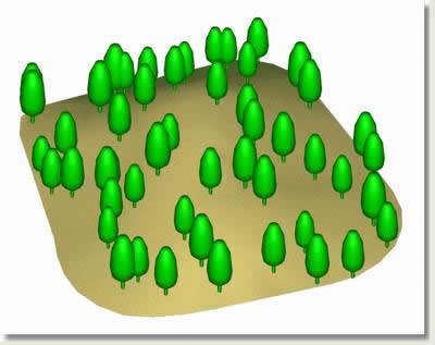
- Display rollout > Check Hide Distribution Object The original terrain is displayed with trees scattered over the surface
Finally, go through the settings on the rollouts experimenting with the Scatter Compound Object
TIP: Create woodland block surfaces with the ShapeMerge Compound Object and populate the surfaces with trees using the Scatter Compound Object. Turn the completed Scatter Objects to editable meshes and apply a multi / sub-object material to show different materials for trunk and canopy (Ref: KV04 Lighting, Materials and Production)
Loft
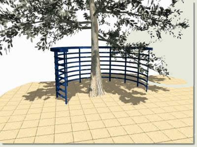
The Loft Compound Object is used extensively in landscape visualisation for creating edge details such as kerbs, curved retaining walls and shaped steps. Also, in the creation of objects that have extruded shapes following paths such as railings or parts of seat architecture
- Open kf201_07.max. This scene contains a spline delineating the path of a kerb and three kerb sections. You will use the Loft Compound Object to 'loft' the kerb sections (called 'shapes') along this path and explore some of the basic Loft Compound Object parameters. Lofting is explained in more detail in KV04
- Select Kerb Path
- Create Panel > Geometry > Compound Objects > Loft
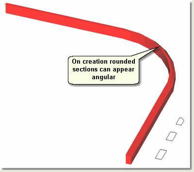
- Creation Method rollout > Get Shape Select Kerb 01 in the viewport. Notice that the kerb shape is 'lofted' along the kerb path
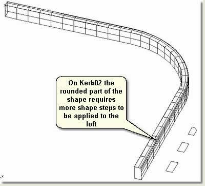
- Still in the command select Kerb 02 then Kerb 03 The loft shape is changed accordingly
- Right click to stop the command
- Notice that the rounded section may appear rather angular. The next stage alters the path steps and shape steps to smooth the angular lines and optimise the number of faces on the loft
- Select Loft01 Change the display mode to Wireframe
- Modify Panel > Skin Parameters rollout > Options
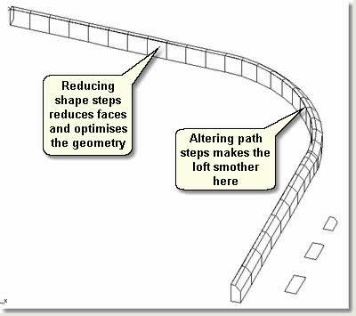
- Practice changing the loft shape by pressing Get Shape and altering the path and shape steps to create the appropriate detail for the loft
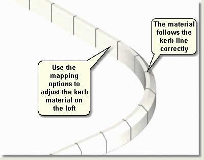
- Open kf201_08.max. This scene contains a loft with a material assigned. You will use the loft mapping option to adjust the kerb materials along the loft object. This is an important material mapping technique used for most curved kerbs, walls, wall tops etc
- Select Loft01 Make sure display mode is Smooth + Highlights
- Modify Panel > Skin Parameters > Mapping Notice that Apply Mapping and Normalize are checked on
- Move the Length Repeat spinner up and down to adjust the kerb material on the kerb loft. Notice how the material follows the line of the path correctly as in real kerb units
TIP: Pay particular attention to the amount of loft faces you accrue in a scene as lofts can use many. Consider using separate lofts for curved segments and straight segments with different amounts of path steps. Also, use basic extrusions for straight segments if the shape is 'box'
TIP: When you are satisfied that the loft will be no longer need modifying convert it to an editable mesh to save on system resources
AEC Extended
AEC Extended Objects are parametric objects enabling the user to quickly create common objects such as railings, walls and foliage and to change the parameters after the object has been created
Below is an image of an AEC Extended Foliage Object and a Railing Object
- Refer to the MAX / VIZ Help for extensive coverage of these objects. Experiment with the Railing Object and Foliage Objects
NOTE: Use these objects with great care. They should be used in close up work and not used liberally due to the high polygon count they create. However, as ever, when used in conjunction with other less detailed models and images they can have a substantial role
Donate to CADTutor
If you found this tutorial useful, you might like to consider making a donation. All content on this site is provided free of charge and we hope to keep it that way. However, running a site like CADTutor does cost money and you can help to improve the service and to guarantee its future by donating a small amount. We guess that you probably wouldn't miss $5.00 but it would make all the difference to us.
Local Navigation
Sponsored Links
The Basics
- Dual Dimensions in a Dim…
- UCSICON Options
- "Best of" Basics: Irreg…
- Tool Palette Basics
- Original Dimension Value
- Possible Solutions to th…
- Avoid Using 'Standard' i…
- Shorten the Plot Scales…
- Update the Source File B…
- User Increment Angles fo…
- Drawing Information
- 'Sign Language'
- Rotate with the Copy Opt…
- Use the INSERT Osnap on…
- To or From the Current L…


