
Creating Terrain Objects
Introduction
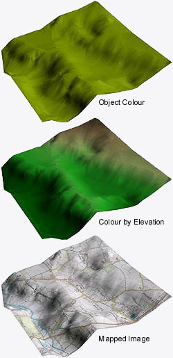
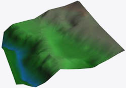
AutoCAD is an excellent tool for basic visualisations of relatively simple objects. It is even possible to create more complex objects such as terrain models with the aid of additional software such as Key TERRA-FIRMA. However, such terrain models are mainly used for the more technical aspects of terrain modelling such as cut-and-fill, visual impact analysis etc. If you want to create a good visualisation of a terrain model, AutoCAD is not the best tool for the job. 3D Studio VIZ R2 has an excellent but simple terrain modeller that can create accurate, triangulated surfaces and solids. Such terrain objects can then be rendered in a number of ways. The illustrations on the right show a terrain object rendered with the object colour (top), with "Colour by Elevation" (middle) and with a mapped bitmap image (bottom). You could even map an aerial photograph onto a terrain object to create a realistic representation of the real world.
Surprisingly, rendered terrains of this sort are relatively easy to create. This tutorial will show you how to import contours (created using AutoCAD) into 3D Studio, how to use the contours to create a terrain object, how to apply colour by elevation and how to map a bitmap image onto the terrain surface. The tutotial also covers the rendering of such objects.
Download Sample Data
If you do not have any AutoCAD contours and a corresponding bitmap or if you wish to follow this tutorial closely, you may like to download the sample files before you continue. If you wish to use your own drawing and image files, skip to the next section. Click on the icons below to download the AutoCAD drawing file Map-Bit.dwg and the JPEG image Map-Bit.jpg. There are two download options, you can either download the two files individually or you can download the smaller compressed file, which contains both. The compressed Zip file can be uncompressed with a utility such as WinZip.
![]() Map-Bit.dwg (116KB) - AutoCAD R14 Drawing File
Map-Bit.dwg (116KB) - AutoCAD R14 Drawing File
![]() Map-Bit.jpg (57KB) - JPEG Image File
Map-Bit.jpg (57KB) - JPEG Image File
![]() Map-Bit.zip (105KB) - Both Files Zipped
Map-Bit.zip (105KB) - Both Files Zipped
Save the files to the directory where you keep your AutoCAD drawing files. If you downloaded the zipped version, you will need to unzip the files before continuing.
The sample drawing file, Map-Bit.dwg contains contours with an exaggerated Z value (X10) so that the effect of the terrain can more clearly be seen. This does not affect the method in any way.
Creating Contour Data
If you intend to use your own contours, there are a couple of points to bear in mind. For best results, contours should be drawn by the method described under the Contour Drawing Technique section of the Ground Modelling tutorial. Once drawn, contours should also be given an elevation as described in the Moving Vertically section of the same tutorial.
Obviously, you can also use digital contour data as provided by the Ordnance Survey or any other mapping organisation. However, the process of terrain creation within 3D Studio is simplified if all contours are drawn on the same layer and there are no other objects in the drawing, so some pre-processing of the data may be required.
 One very important issue is that 3D Studio VIZ R2 is not compatible with AutoCAD 2000, 200i and 2002 drawings. You must, therefore, save your contour drawing as a Release 14 drawing. File
![]() Save As… and select AutoCAD R14 (*.dwg) from the "Save as type" list. This is important because if you try to import an AutoCAD 2000 drawing into VIZ R2, nothing happens, you get no error message and this can be very confusing.
Save As… and select AutoCAD R14 (*.dwg) from the "Save as type" list. This is important because if you try to import an AutoCAD 2000 drawing into VIZ R2, nothing happens, you get no error message and this can be very confusing.
Importing the .DWG File
 Start 3D Studio VIZ R2 by double-clicking the program icon, shown above. When 3DS VIZ has loaded, select File
![]() Import… from the pull-down menu. The Select File to Import dialogue box appears. First, use the drop-down list at the bottom of the dialogue box to set "Files of type" to "AutoCAD (*.DWG)", then navigate your way to the file you want to import. Highlight the file by clicking it once (the dialogue box should now look similar to the one in the illustration on the left) and then click the "Open" button.
Import… from the pull-down menu. The Select File to Import dialogue box appears. First, use the drop-down list at the bottom of the dialogue box to set "Files of type" to "AutoCAD (*.DWG)", then navigate your way to the file you want to import. Highlight the file by clicking it once (the dialogue box should now look similar to the one in the illustration on the left) and then click the "Open" button.
 When the DWG Import dialogue box appears, click the "Completely replace current scene" radio button and click the "OK" button to proceed. This effectively creates a new 3D Studio model from your AutoCAD original. The "Merge objects…" option can be used to add AutoCAD drawings to existing 3D Studio models.
The Import AutoCAD DWG File dialogue box then appears. This allows you to set a whole range of variables which determine how the AutoCAD drawing will be interpreted when it is transformed into a 3D Studio model.
Most of the available options are self explanatory and you can decide for yourself how you want the model to be generated. For the purpose of this exercise, just ensure that the "Derive Objects By" parameter is set to "Layer", you can leave all of the other options set to their defaults. Click the "OK" button to start the import process.
The import process is not instantaneous. Most AutoCAD drawings will just take a few moments to convert but complex drawings with lots of faces can take a few minutes or more so you will need to be patient. 3DS VIZ shows a progress bar at the bottom of the screen. When the import has been completed, you will see your AutoCAD contours displayed within the 3D Studio Perspective view-port. If you do not see any contours, make sure that you saved your drawing in Release 14 format. If you have not used 3D Studio before, take a few moments to familiarise yourself with the layout of the program interface, it is quite different to AutoCAD.
Creating the Terrain Object
Creating a terrain object with 3D Studio VIZ R2 is a simple, one-step process. Once your contours have been imported, click on them to select them. Since your contours were all on the same AutoCAD drawing layer and since you specified objects to be derived by layer, your contours now form a single 3D Studio object. Clicking on any contour will select the entire set of contours. You should see a white "bounding box" appear around the contour set.  Notice also that the object name shown in the Control Panel is derived from the layer name. For example, if your contour layer was called "Contours", the contour object will be called "CONTOURS.01".
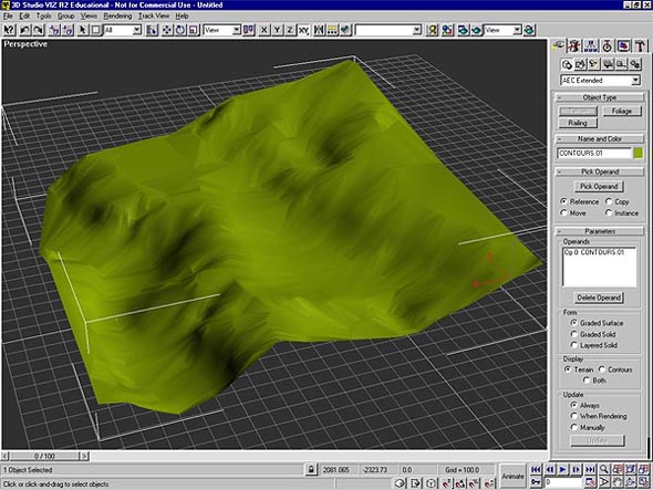
Click the Create tab ![]() on the Control Panel if it is not already selected and then click the Geometry
on the Control Panel if it is not already selected and then click the Geometry ![]() button. Click the arrow on the drop-down list below the Geometry button and select "AEC Extended". The Control Panel should now look like the illustration on the right. If the "Terrain" button is greyed-out, your contour object is not selected. Select the contour object to activate the button. To create the terrain object, simply click the "Terrain" button. In a few moments a triangulated surface will be created.
button. Click the arrow on the drop-down list below the Geometry button and select "AEC Extended". The Control Panel should now look like the illustration on the right. If the "Terrain" button is greyed-out, your contour object is not selected. Select the contour object to activate the button. To create the terrain object, simply click the "Terrain" button. In a few moments a triangulated surface will be created.
If the current view of the terrain object is not satisfactory, use the Arc Rotate Selected ![]() , Field-of-View
, Field-of-View ![]() and Pan
and Pan ![]() buttons, located at the bottom right-hand corner of the screen to adjust it. If you are familiar with AutoCAD 2000, you will recognise the Arc Rotate Selected tool as being similar to the 3D Orbit tool. Your computer screen should now look something like the one shown below.
buttons, located at the bottom right-hand corner of the screen to adjust it. If you are familiar with AutoCAD 2000, you will recognise the Arc Rotate Selected tool as being similar to the 3D Orbit tool. Your computer screen should now look something like the one shown below.
Terrain Parameters
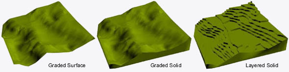
 There are a couple of terrain parameters that are worth considering at this stage. If you look at the Parameters section of the Control Panel, you should see options under the headings of "Form" and "Display" (see the illustration on the right). The Form options allow you to generate the terrain object as either a Graded Surface (the default), a Graded Solid or as a Layered Solid. The illustration below shows the effects of the various options. 3D Studio treats your original contours and the new triangulated surface as the same object. The Display options enable you to display the terrain only, the contours only or both terrain and contours.
Once you have completed the terrain creation process, the terrain options disappear from the Create tab on the Control Panel but you can still access the options from the Modify tab ![]() . In fact, you can access the terrain options at any time by selecting the terrain object and clicking the Modify tab.
. In fact, you can access the terrain options at any time by selecting the terrain object and clicking the Modify tab.
Once you have successfully created a terrain object, you may want to apply a material to improve the quality of the render. There are numerous options but this tutorial considers two that are particularly appropriate for terrain objects. The first option, Colour by Elevation is described in the next section of this tutorial. The second option, Adding an Image Map is described below.
Colour by Elevation
 To start the Colour by Elevation process, select the terrain object, click the Modify tab
 ![]() on the Control Panel and expand the Colour by Elevation rollup by clicking on the button. The button is right at the bottom of the Control Panel and you may have to scroll down to find it. As you can see from the illustration on the right, the Control Panel shows the maximum and minimum elevations (Z values) and the reference elevation. The reference elevation controls where 3DS VIZ places the elevation datum. By default, this value is set to the minimum elevation of the terrain object. However, 3DS VIZ treats terrain elevations below the reference elevation as water and those above as land.
on the Control Panel and expand the Colour by Elevation rollup by clicking on the button. The button is right at the bottom of the Control Panel and you may have to scroll down to find it. As you can see from the illustration on the right, the Control Panel shows the maximum and minimum elevations (Z values) and the reference elevation. The reference elevation controls where 3DS VIZ places the elevation datum. By default, this value is set to the minimum elevation of the terrain object. However, 3DS VIZ treats terrain elevations below the reference elevation as water and those above as land. 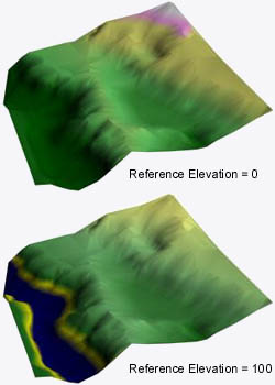 You can create instant results by clicking the "Create Defaults" button. The illustrations on the left show the difference between setting the reference elevation to 0 and to 100 and then clicking on Create Defaults. When the reference elevation is set to 100, elevations below 100 are blue in colour, whilst those above are green. Between the two is a thin band of yellow that mimics the effect of a shoreline or beach. When the reference elevation is set to 0, all of the terrain object is considered to be land and base elevations and colours are assigned accordingly. Getting 3DS VIZ to create default settings for you is a good way to start the Colour by Elevation process. However, you will often need to modify the default settings in order to create a more appropriate colour range. Notice that in the illustration above, 3DS VIZ is quite happy to suggest that our terrain object might have a snow capped peak, even if the data is derived from southern England. The next section of the tutorial describes how to modify the colour zones.
Modifying Colour Zones
Colour zones are defined by specifying just two parameters, namely, Base Elevation and Base Colour. You also have the option of having the colour blend with the one above. To modify a colour zone, simply highlight it in the "Zones by Base Elevation" list and enter an appropriate base elevation using the "Base Elev" edit box. To change the colour, pick on the "Base Color" box and select an appropriate colour from the Colour Selector dialogue (shown below). The Colour Selector allows you to define a colour using RGB values (Red, Green, Blue), HSL values (Hue, Saturation, Lightness) or simply by picking on any of the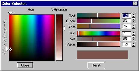 colour areas. Click the "Close" button on the Colour Selector to assign the chosen colour to the colour zone. When you have entered the base elevation and selected the base colour, decide whether you want the colour to blend with the zone above and pick the appropriate radio button. To apply the new settings, click on the "Modify Zone" button. You should be able to view the changes you have made on the terrain object almost instantly, depending upon the complexity of the object and the speed of your computer.
 To add a new colour zone to the list, go through the same process as described above but click on the "Add Zone" button. A new colour zone will appear in the list and once again the terrain object will update to show the effect of the new colour zone. You can also delete a zone by highlighting it in the list and then clicking on the "Delete Zone" button. Eventually, you should be able to create a set of colour zones of varying band depths and in various colours that mimics the landform you want to create. The colour zones displayed in the illustration above were created by modifying the default colour zones and adding three
 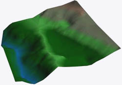 new ones, a total of eight colour zones in all. In order to give a smooth colour transition between one zone and the next, all zones were set to "Blend to Color Above". To give you an idea of the difference this makes, the illustration on the right uses the same colour zones but with each zone set to "Solid to Top of Zone". As you can see, the zones are more clearly defined, which would be good for an elevation analysis but the effect is less realistic.
You can remove Colour by Elevation from a terrain object by deleting all of the colour zones associated with it. The terrain appearance will the return the the object colour. However, there is now way to restore your colour zones after you have deleted them.
Adding an Image Map
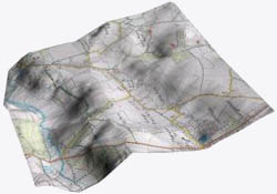
As you have seen above, setting Colour by Elevation can create quite realistic terrain effects. However, you may want to improve upon this by adding an image map to the terrain object. Image maps can be any bitmap image, so you could use an aerial photograph or a cartographic map of the same area. Adding an image map to a terrain object is a relatively simple process with one proviso. The area (of the real world) covered by the contour drawing and the bitmap image must be the same in order that the bitmap is correctly georeferenced with respect to the terrain object. Providing this condition is satisfied, all will be well. The sample file Map-Bit.jpg covers exactly the same area as the drawing file Map-Bit.dwg. In fact, the contours were traced from the bitmap image in AutoCAD. This is a sure-fire way of making sure that the two match up correctly.
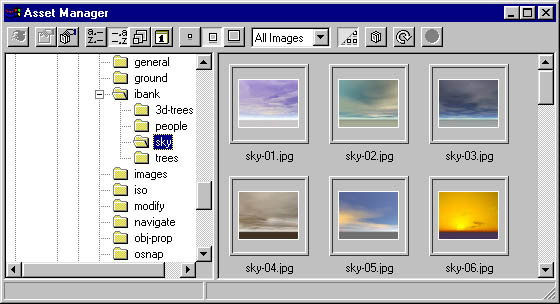
To map the image onto the surface of the terrain object, start by clicking the Utilities tab ![]() on the Control Panel and then click on the "Asset Manager" button. When the Asset Manager appears, use the Explorer style window on the left to navigate your way to the folder where your bitmap image is stored. Clicking on the folder displays all available image files in the folder as thumbnail images in the right hand window. The illustration above shows the Asset Manager with the Map-Bit.jpg file highlighted. You can change the size of the thumbnail images using the Display Thumbnail buttons on the Asset Manager toolbar.
on the Control Panel and then click on the "Asset Manager" button. When the Asset Manager appears, use the Explorer style window on the left to navigate your way to the folder where your bitmap image is stored. Clicking on the folder displays all available image files in the folder as thumbnail images in the right hand window. The illustration above shows the Asset Manager with the Map-Bit.jpg file highlighted. You can change the size of the thumbnail images using the Display Thumbnail buttons on the Asset Manager toolbar.
Position the Asset Manager window so that you can see both the required image thumbnail and the terrain object. Drag and drop the image thumbnail onto the terrain object. The terrain object may change colour as the image map is applied but the image does not yet display correctly because the mapping default settings are not designed for this particular effect. If you have assigned Colour by Elevation to the terrain object, the image map may not show in the Perspective window. However, the image map has been assigned and it will display in a render window if the view is rendered. See Rendering, below for details.
Setting the Mapping
 To set the image mapping so that the bitmap image appears across the whole surface of the terrain object, we need to use the Material Editor. Click the Material Editor button
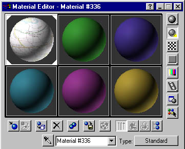
 ![]() to display the Material Editor. The Material Editor, shown on the right displays six default materials. What we need to do is to select the image map we have just assigned to the terrain object and modify it. Select the image map from the terrain object by clicking on the Pick Material from Object button
to display the Material Editor. The Material Editor, shown on the right displays six default materials. What we need to do is to select the image map we have just assigned to the terrain object and modify it. Select the image map from the terrain object by clicking on the Pick Material from Object button![]() . Move the cursor over the terrain object, the cursor changes to an eyedropper. Pick the terrain object with the eyedropper. The sphere in the top left-hand corner of the Material Editor now changes to show the image and the new material is assigned a unique number.
. Move the cursor over the terrain object, the cursor changes to an eyedropper. Pick the terrain object with the eyedropper. The sphere in the top left-hand corner of the Material Editor now changes to show the image and the new material is assigned a unique number.
 Next, scroll to the bottom of the Material Editor and expand the Maps rollup by clicking on the "Maps" button. You should see a tick in the "Diffuse" check box and the image filename displayed on the Map button.
Click the button displaying the image filename on the Maps rollup and the Material Editor changes to display a new set of parameters.  In the Coordinates rollup, click on the "Mapping" drop-down list and select "Planar from Object XYZ". The terrain object in the Perspective view window should now change to display the bitmap correctly.
 If you have added Colour by Elevation to the terrain object, the bitmap appears transparently over the colour zones in the Perspective view. However, when the terrain is rendered only the bitmap will be seen. Material assignments override Colour by Elevation settings when terrain objects are rendered.
The illustration on the left shows the final terrain graded surface with the bitmap image mapped to it.
 You can remove an image map from an object at any time using the Material/Map Browser. To display the Material/Map Browser, select Tools
![]() Material/Map Browser… from the pull-down menu. Set the "Browse From" option to "New" and then drag-and-drop the "
Material/Map Browser… from the pull-down menu. Set the "Browse From" option to "New" and then drag-and-drop the "![]() NONE" item onto the terrain object. The image map is removed from the object but it remains in the Material Editor along with any settings you have made. To re-map the object, simply open the Material Editor and then drag-and-drop the material back onto the terrain.
NONE" item onto the terrain object. The image map is removed from the object but it remains in the Material Editor along with any settings you have made. To re-map the object, simply open the Material Editor and then drag-and-drop the material back onto the terrain.
Rendering a View
All of the required settings for creating a rendered image of your terrain object can be set using the Render Scene dialogue box, illustrated below. To display the dialogue box, click the Render Scene button ![]() on the main toolbar. You will need to set a number of options in the Common Parameters rollout.
on the main toolbar. You will need to set a number of options in the Common Parameters rollout.
In the "Time Output" area, click on the "Single" radio button if this is not already selected. This tells 3DS VIZ to render a single frame. As you can see, other options exist which allow you to render an animation. See the Rendering the Animation section of the Walkthrough tutorial for more details.
You can now use the "Output Size" area of the rollout to specify the size of the rendered image in pixels. You can either set the size manually using the "Width" and "Height" edit boxes or you can use one of the pre-set options by clicking the appropriate button. For the purposes of this exercise, set the size to 320x240 by clicking the "320x240" button.
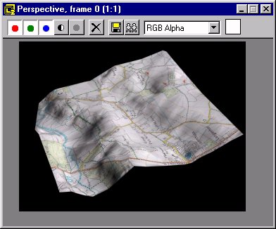 Deselect the "Save File" option in the "Render Output" area if it is checked. Finally, make sure that the view you want to render is shown in the "Viewport" drop-down list. If you are following the tutorial, this viewport should be set to "Perspective". To start the render process, click the "Render" button. Two new windows now appear on your screen. The Perspective window displays the rendered image as it is rendered and the Rendering window shows the progress of the render, giving details of time taken. When the render is complete, the Render window disappears but the Perspective window remains so that you can look at the rendered image. If you are following this tutorial and you have applied the image map, your Perspective window should look similar to the one in the illustration above. So far we have created a small rendered image and viewed it on screen. This process is very useful for previewing a render whilst you are working on a drawing. Once you have made the settings in the Render Scene dialogue, you can preview renders as you work on your drawing by clicking on the Quick Render button
 ![]() . This by-passes the dialogue and renders using the existing settings. Eventually though, you will probably want to render at a larger size and save the image to a file.
. This by-passes the dialogue and renders using the existing settings. Eventually though, you will probably want to render at a larger size and save the image to a file.
Rendering to a File
Rendering to a file requires you to specify a filename, to choose a file format and to make any necessary settings that may be specific to that file format.
Click the Render Scene button ![]() to display the Render Scene dialogue box. Make the settings as for rendering a view except, click on the "Save File" check box in the "Render Output" area of the rollup. Next, click on the "Files…" button to display the Render Output File dialogue box.
to display the Render Scene dialogue box. Make the settings as for rendering a view except, click on the "Save File" check box in the "Render Output" area of the rollup. Next, click on the "Files…" button to display the Render Output File dialogue box.
Use the "Drives" drop-down list and the "Folders" window on the right to navigate your way to the folder where you want to save the image file. Then, use the "List files of type" drop-down list to select the required file format and enter the name of the file you want to create in the "File name" edit box. Finally, click on the "Setup…" button to make any necessary settings specific to the file format you have chosen. For example, if you have chosen the JPEG file format, setup can be used to control the amount of compression. When you have made the required settings, click the "OK" button to return to the Render Output File dialogue and then "OK" again to return to the Render Scene dialogue. You should now see the specified file name and path displayed. To render, simply click on the Render button. 3DS VIZ renders the image to a window and simultaneously writes the data to file.
You will probably have noticed that your rendered images all have a black background. This is the default colour for renders. It is, however, very easy to change the colour. The next section of the tutorial deals with this topic.
Changing the Background Colour
The render background colour is controlled from the Environment dialogue box. To display the Environment dialogue box, select Rendering![]() Environment… from the pull-down menu.
Environment… from the pull-down menu.
 The "Background" area of the "Common Parameters" rollup, shown on the left, displays the current background colour in a rectangular window. Since you have not yet set a colour, this window will be black. To change the background colour, click on the colour window to display the Colour Selector dialogue. Choose a colour from the palette and then click the "Close" button. The new colour now displays in the background colour window. To see the results of your change, render the view.
Changing the colour of the render background is a good way to liven up your rendered images. However, to really give them some punch, try using an environment map.
Using an Environment Map
Environment maps are images used as backdrops to rendered views. Almost any bitmap in most of the standard file formats can be used as an environment map. This means that you could even use a photograph of an existing site and use it as a backdrop to show your proposals.
The simplest way to apply an environment map is to first find the image you want to use with the Asset Manager. Click the Utilities tab ![]() on the Control Panel and then click the "Asset Manager" button. Navigate your way to the folder where your images are stored and wait for the image thumbnails to display. Next, open the Environment dialogue box, select Rendering
on the Control Panel and then click the "Asset Manager" button. Navigate your way to the folder where your images are stored and wait for the image thumbnails to display. Next, open the Environment dialogue box, select Rendering![]() Environment… from the pull-down menu. Notice that the Environment Map button currently displays the word "None", meaning that no environment map has been specified.
Environment… from the pull-down menu. Notice that the Environment Map button currently displays the word "None", meaning that no environment map has been specified. To assign an image as an environment map, drag the thumbnail image you want from the Asset Manager and drop it onto the Environment Map button in the Environment dialogue. When you have done this a small dialogue box appears and prompts you to enter a name for the new material you are creating. Enter a name and then click the "OK" button. The Environment Map button in the "Background" area of the Environment dialogue box changes to display the material name and the image file name. You can now close the Asset Manager but keep the Environment dialogue open.
 You have now assigned an environment map and if you render the view you will see your bitmap used as a background image. However, the image has been applied with default mapping settings (spherical environment), which may not be what you want. In order to change environment map settings, you must first drop your new material into the Material Editor.
Click on the Material Editor button ![]() to display the Material Editor. Now, click and drag the Environment Map button from the Environment dialogue box and drop it on top of one of the spheres in the Material Editor. A small dialogue box appears and asks you if this material is an instance or a copy. Click the "Instance" radio button if it is not already checked and click "OK". The sphere in the Material Editor now changes to display your background image.
to display the Material Editor. Now, click and drag the Environment Map button from the Environment dialogue box and drop it on top of one of the spheres in the Material Editor. A small dialogue box appears and asks you if this material is an instance or a copy. Click the "Instance" radio button if it is not already checked and click "OK". The sphere in the Material Editor now changes to display your background image.
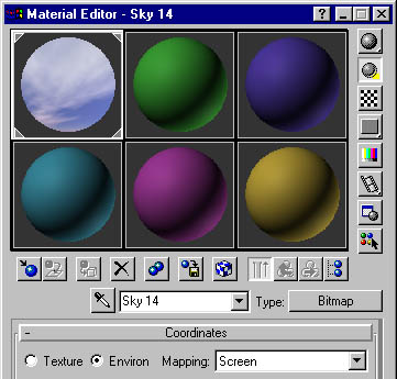 If you now look at the Coordinates rollup, you will see that the mapping is set to Spherical Environment. This is the default setting and means that the background image is mapped onto the inside surface of a sphere and surrounds the scene completely. This type of mapping is great for camera animations where the direction of view is constantly changing. It is not particularly good if you just want a single rendered view and you want to see the whole of the background image. So, click the down arrow on the "Mapping" drop-down list and select "Screen". The screen option maps the whole image to the render background. The sphere image in the Material Editor changes to display the new settings. Experiment with the various mapping settings and do some renders to see the effect they have on the final image.
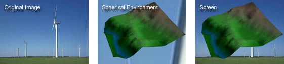
The illustration above shows the effect of the Spherical Environment and Screen mapping options on a background image. If you need some background images to work with, don't forget to look at the Image Bank section of this site. In particular, the sky images may be useful.
Donate to CADTutor
If you found this tutorial useful, you might like to consider making a donation. All content on this site is provided free of charge and we hope to keep it that way. However, running a site like CADTutor does cost money and you can help to improve the service and to guarantee its future by donating a small amount. We guess that you probably wouldn't miss $5.00 but it would make all the difference to us.
Local Navigation
Sponsored Links
The Basics
- Dual Dimensions in a Dim…
- UCSICON Options
- "Best of" Basics: Irreg…
- Tool Palette Basics
- Original Dimension Value
- Possible Solutions to th…
- Avoid Using 'Standard' i…
- Shorten the Plot Scales…
- Update the Source File B…
- User Increment Angles fo…
- Drawing Information
- 'Sign Language'
- Rotate with the Copy Opt…
- Use the INSERT Osnap on…
- To or From the Current L…


