
Creating a Walkthrough
Introduction
AutoCAD is a very flexible tool and it can be used for a wide variety of tasks. However, one thing you can't do with AutoCAD is animate a 3D model. You can, of course, create slides of perspective views and show them one after the other using a script file (see "Perspectives, Slides and Scripts" for details) but this doesn't begin to approach the quality of animation which can be produced with the aid of some other software utilities.
This tutorial shows how to create an animated walkthrough of your AutoCAD 3D model using 3DS MAX 5. All you need to start is an AutoCAD drawing with some 3D content. The end result will be a .AVI file which can be viewed on any Windows PC. AVI files can also be embedded within PowerPoint presentations along with text and other graphics to really demonstrate your design proposals.
Download Sample Data
If you do not have a 3D AutoCAD drawing to use or if you wish to follow this tutorial closely, you may like to download the sample file before you continue with the tutorial. If you wish to use your own drawing, skip to the next section. Click on the icon below to download the AutoCAD drawing file 3D-Trees.dwg. There are two download options, you can either download the native AutoCAD drawing file or you can download the smaller compressed version. The Zip file can be uncompressed with a utility such as WinZip.
![]() 3D-Trees.dwg (30KB) - AutoCAD R14 Drawing File
3D-Trees.dwg (30KB) - AutoCAD R14 Drawing File
![]() 3D-Trees.zip (7KB) - Zipped Drawing File
3D-Trees.zip (7KB) - Zipped Drawing File
Save the file to the directory where you keep your AutoCAD drawing files. If you downloaded the zipped version, you will need to unzip the drawing file first.
Importing the .DWG File
 Start 3DS MAX. When the application has loaded, select File
![]() Import… from the pull-down menu. The Select File to Import dialogue box will appear. First, use the drop-down list at the bottom of the dialogue box to set "Files of type" to "AutoCAD (*.DWG)", then navigate your way to the file you want to import. Highlight the file by clicking it once and then click the "Open" button.
Import… from the pull-down menu. The Select File to Import dialogue box will appear. First, use the drop-down list at the bottom of the dialogue box to set "Files of type" to "AutoCAD (*.DWG)", then navigate your way to the file you want to import. Highlight the file by clicking it once and then click the "Open" button.
 When the DWG Import dialogue box appears, click the "Completely replace current scene" radio button and click the "OK" button to proceed. This effectively creates a new MAX drawing from your AutoCAD original. The "Merge objects…" option can be used to add AutoCAD drawings to existing MAX drawings. This can be useful if you are constructing a number of elements in AutoCAD and then using MAX to assemble them into a scene prior to render or animation. However, in this case we have a single drawing object, so the "Completely replace…" option will do just fine.
The Import AutoCAD DWG File dialogue box allows you to set a whole range of variables which determine how the AutoCAD drawing will be interpreted when it is transformed into a MAX model.
Most of the available options are self explanatory and you can decide for yourself how you want the model to be generated. For the purpose of this exercise you can leave all of the options set to their defaults, so simply click the "OK" button to accept the current settings.
The import process is not instantaneous. Most AutoCAD drawings will just take a few moments to convert but complex drawings with lots of faces can take a few minutes or more so you will need to be patient. MAX shows a progress bar at the bottom of the screen so that you can see the percentage of the process which is completed. I must admit that I have found this to be slightly unreliable. However, once the import has been completed, you will see your AutoCAD drawing elements displayed within the 3D Studio view-ports.
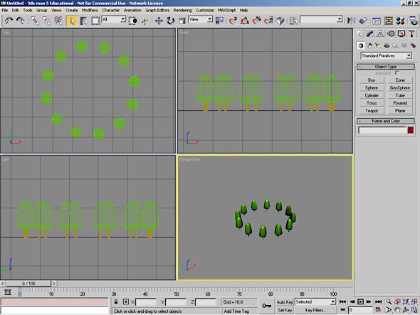
If you are using the sample drawing file, your screen should now look like the one above. If you have not used 3DS MAX before, take a few moments to familiarise yourself with the layout of the program interface, it is quite different to AutoCAD.
Walkthrough Overview
Essentially, creating an animated walkthrough with MAX is a 5 step process. First of all we must define the path of the walk by drawing a line (Drawing a Path). Secondly we must create a camera which will record the animation (Creating a Camera). The next step is to tell 3D Studio how long the walk should take (Time Configuration). We must then assign the camera to the path (Assigning the Camera to the Path) and finally we must render the animation to create the .AVI file (Rendering the Animation). Each of these steps is covered in the following sections.
Drawing a Path
Before you begin drawing a walkthrough path you should decide where you would like the path to start, end and where you would like it to go in between.
To begin drawing a line, click the Create tab ![]() in the Command Panel and then the Shapes button
in the Command Panel and then the Shapes button ![]() . You should then see two columns of buttons on the "Object Type" rollout. Click on the "Line" button. Before you start to draw the line, there are a couple more settings you need to make. In order to ensure that the animation flows smoothly you need to draw a line which doesn't have any sharp corners. To do this, find the "Creation Method" rollout on the Command Panel and set both the "Initial Type" and "Drag Type" options to "Smooth" by clicking on the appropriate radio buttons. You are now ready to start drawing the path.
. You should then see two columns of buttons on the "Object Type" rollout. Click on the "Line" button. Before you start to draw the line, there are a couple more settings you need to make. In order to ensure that the animation flows smoothly you need to draw a line which doesn't have any sharp corners. To do this, find the "Creation Method" rollout on the Command Panel and set both the "Initial Type" and "Drag Type" options to "Smooth" by clicking on the appropriate radio buttons. You are now ready to start drawing the path.
 Although you can draw in any of the viewports, it will be easiest to draw the animation path in the Top viewport since this shows a plan view of the drawing. Effectively, drawing lines in MAX is the same as drawing Polylines or Splines in AutoCAD. Draw a simple line like the one shown in the illustration by clicking two or more points and then right-click to finish. When drawing the line, try to use as few points as possible to describe the camera path. The fewer points you use, the smoother the motion of the camera will be. The Top viewport should now look similar to the illustration on the right.
Finally you need to give the path an elevation. If you look at the images in the Front and Left viewports you will notice that the path currently lies on the ground plane, it has an elevation of zero. We need to move the path vertically to human eye height so that the walkthrough will be seen from a real persons perspective.
![]() Click on the Select and Move button on the toolbar and then select Tools
Click on the Select and Move button on the toolbar and then select Tools![]() Transform Type-In from the pull-down menu or hit the F12 key on the keyboard. The Transform Type-In dialogue box appears. Set the Z value in the "Absolute: World" section to 1.7 (remember that we are working in metres) and press the
Transform Type-In from the pull-down menu or hit the F12 key on the keyboard. The Transform Type-In dialogue box appears. Set the Z value in the "Absolute: World" section to 1.7 (remember that we are working in metres) and press the ![]() key on the keyboard. You will see the path move up in the Front and Left viewports. Close the Transform Type-In dialogue box. You have now drawn the animation path.
key on the keyboard. You will see the path move up in the Front and Left viewports. Close the Transform Type-In dialogue box. You have now drawn the animation path.
Adding a Camera
The next part of the process involves adding a Camera to the MAX model. Click the Create tab if it is not already selected and then click on the Cameras button ![]() . The Control Panel will change to show the camera parameters. First of all you need to select the type of camera. On the "Object Type" rollout, click on the "Free" button to define a Free Camera. Place the camera in the Left viewport by clicking just above the model. Creating a Free camera in the Left viewport will automatically align the camera's line of sight with the positive world X axis. You need to do this so that the camera follows the path correctly.
. The Control Panel will change to show the camera parameters. First of all you need to select the type of camera. On the "Object Type" rollout, click on the "Free" button to define a Free Camera. Place the camera in the Left viewport by clicking just above the model. Creating a Free camera in the Left viewport will automatically align the camera's line of sight with the positive world X axis. You need to do this so that the camera follows the path correctly.
 You now need to set the camera parameters. The first choice to make is the focal length of the camera lens. You can set the focal length manually using the "Lens" edit box on the "Parameters" rollout or you can set the field of view with the "FOV" edit box. However, you will usually want to use one of the stock lenses. Choose the lens you want by clicking on the appropriate button in the "Stock Lenses" section. Bear in mind that a 50mm lens will give you the equivalent field of view of the human eye. Focal lengths shorter than 50mm will give a wide angle view and focal lengths longer than 50mm will give a telephoto view. You will see that the stock lenses range from 15mm (Fish Eye) to 200mm which gives you a wide range of options. It's worth experimenting with focal lengths, some wide angle effects can be quite dramatic. For the purposes of this exercise, click on the "28mm" button to select a 28mm lens. Finally, check the "Show Cone" option so that the view cone of the camera will be displayed even when the camera is not selected. This will help you to determine what objects will be in the field of view at any particular time. The camera set-up is now complete and the view in the Left viewport should look similar to the illustration on the left.
Time Configuration
Having created a path and a camera, you now need to tell MAX how long it should take for the camera to travel along the path from start to finish. Time is defined by setting a frame rate for the animation (number of frames per second) and then specifying the total number of frames. For example, if you set the frame rate to 15 frames per second and specify the number of frames to be 150, this would result in 10 seconds of animation.
 All of the time related settings are made using the Time Configuration dialogue box. To display the dialogue box, click the Time Configuration button
 ![]() on the toolbar at the bottom right to the screen.
on the toolbar at the bottom right to the screen.
First of all, set the frame rate. Click on the "Custom" radio button in the "Frame Rate" section of the dialogue box and set the frame rate to 15 using the "FPS" edit box. Although video runs at 30 frames per second and film at 24 frames per second, a setting of 15 frames per second is perfectly adequate for computer animation. Many computers will not be able to display all animation frames at faster rates and this will cause frames to be dropped which leads to a jerky animation.
In the "Animation" section of the dialogue box, set the "End Time" to 180. This will give 12 seconds of animation at 15 frames per second. Click the "OK" button to complete time configuration. Notice that the animation slider at the bottom left of the screen now reads "0/180" this tells you that the current time segment is set to 180 frames and that the slider is currently set to the position of the first frame, frame zero.
It's worth pointing out at this point that although you specified 12 seconds at 15 frames per second, MAX sets the Frame Count to 181. This is because the first frame is always frame 0. This might seem confusing but it is somewhat of a convention and you will find the same anomaly in other animation applications.
Assigning the Path to the Camera
  |
In order to assign the line as a path for the camera, we need to set the camera to follow a path and then to select the line to form that path. Take care to follow all of the steps in this section correctly. Assigning controllers is not a particularly intuitive affair and it is easy to make a mistake.
To start, make sure that the camera is currently selected. Click on the Motion tab ![]() on the Control Panel. If the camera is selected, you will see the object name "Camera01" in the box at the top of the Control Panel. If you do not see this, click on the camera to select it before proceeding.
on the Control Panel. If the camera is selected, you will see the object name "Camera01" in the box at the top of the Control Panel. If you do not see this, click on the camera to select it before proceeding.
 Click on the Assign Controller title bar on the control Panel to expand the Assign Controller rollout. You will see a list of the various transform options. Select Position : PositionXYZ from the list. The Assign Controller button
 ![]() now becomes active, click this button to display the Assign Position Controller dialogue box, shown on the right. Select Path Constraint from the list and click the OK button.
now becomes active, click this button to display the Assign Position Controller dialogue box, shown on the right. Select Path Constraint from the list and click the OK button.
The Path Parameters rollout will now appear in the Comand Panel (see illustration below). Click on the Add Path button in the Path Parameters section. Now select the line you drew earlier. It's probably most easy to do this in the Top viewport. You should see the camera jump to the first point you picked when you drew the line and the name Line01 will appear as a Target in the Path Parameters list.
 Finally, check the Follow box in the Path Options section. You may see the camera orientation change slightly so that it now points along the line. The Follow option must be checked so that the camera and it's target move along the line correctly. The Top viewport should now look similar to the one shown below.
 You can check that all options have been correctly set by clicking and dragging the animation slider at the bottom of the screen. You should see the camera move along the path in all four viewports. Just take a few moments to check that everything looks OK. When you are satisfied that the settings have been made correctly, move on to the next section. If there is a problem, repeat the steps in this section, taking care not to miss anything out.
Previewing the Animation
Previewing the animation is not a fundamental part of the process, however, it is advisable to do so before rendering the animation. Rendering can take a long time depending upon the size of window and length of animation. This may be hours rather than minutes, so it is a good idea to get it right first time!
First of all we need to set one of the viewports so that we see the view from the camera. Click on the Perspective viewport to make it the active viewport and then simply press the "C" key on the keyboard. The name of the viewport is changed to Camera01 and the view is changed to the current camera position.
To preview the animation, click the Play Animation button ![]() on the animation toolbar at the bottom right of the screen. You should see the animation play in the Camera01 viewport. The animation will loop (repeat) until you click the Stop Animation button
on the animation toolbar at the bottom right of the screen. You should see the animation play in the Camera01 viewport. The animation will loop (repeat) until you click the Stop Animation button ![]() . When the animation is stopped, you can set it back to frame zero either by dragging the animation slider over to the left or by clicking the Go to Start button
. When the animation is stopped, you can set it back to frame zero either by dragging the animation slider over to the left or by clicking the Go to Start button ![]() .
.
Modifying the Path
 Very often, you will find that the animation is not quite what you wanted. Maybe the motion is not very smooth or maybe the orientation of the view is not quite right. Whatever the reason, you can modify the path in order to correct the problem. This is fairly easy and gives you great control over the final result.
To modify the path, select the line and then click on the Modify tab ![]() on the Control Panel. Select Edit Spline from the Modifier List. You should now see that each vertex on the line is marked with a small cross. At this point you have a number of options available to you. You can move individual vertices by clicking the Select and Move button
on the Control Panel. Select Edit Spline from the Modifier List. You should now see that each vertex on the line is marked with a small cross. At this point you have a number of options available to you. You can move individual vertices by clicking the Select and Move button ![]() on the main toolbar and then clicking and dragging the vertex marks. This works in a similar way to editing Polylines using grips in AutoCAD. You can also delete vertices by clicking on them and then clicking the "Delete" button in the Geometry rollout or by hitting the Delete key on the keyboard.
on the main toolbar and then clicking and dragging the vertex marks. This works in a similar way to editing Polylines using grips in AutoCAD. You can also delete vertices by clicking on them and then clicking the "Delete" button in the Geometry rollout or by hitting the Delete key on the keyboard.
Remember that you can use the position gizmo to comstrain movement of the vertices in the X or Y direction. The illustration below shows the gizmo as it appears when movement is constrained to the XY Plane. Bear in mind that just as you can move the position of the vertices in the XY Plane fron the Top viewport, you can move the position in other planes as well  using the other viewports. For example, you could use the Left viewport to move the path vertices up or down. By this method, you can cause the camera to rise or fall during the animation.
Obviously, you can preview the animation again at any point in the editing process. In general, fewer vertices will give a smoother animation so it's a good idea to delete any unwanted vetrices. When you have completed the required edits, preview the animation again to see the effect. The illustration above shows the path after modification. Bear in mind that if you shorten or lengthen the path, the animation will run slower or faster respectively.
Rendering the Animation
The first thing you must do is click in the Camera01 viewport to make it the current active viewport if it isn't so already.
![]() All of the required settings for rendering your animation can be set using the Render Scene dialogue box, illustrated below. To display the dialogue box, click the Render Scene button on the main toolbar. You will need to set a number of options in the Common Parameters rollout.
All of the required settings for rendering your animation can be set using the Render Scene dialogue box, illustrated below. To display the dialogue box, click the Render Scene button on the main toolbar. You will need to set a number of options in the Common Parameters rollout.
First of all, click on the "Active Time Segment" radio button in the "Time Output" section of the dialogue box. This tells 3D Studio to render all frames in the currently defined animation. As you can see, other options exist which allow you to render just a part of the animation.
Next, you must specify the size of the animation window in pixels. You can either set the size manually using the Width and Height edit boxes or you can use one of the preset options by clicking the appropriate button. For the purposes of this exercise, set the size to 320x240 by clicking the "320x240" button.
 You can skip the Render Options section since the default settings will work fine and go straight to the Render Output section. We need to specify a file name to write the render information to. Click on the "File…" button to display the Render Output File dialogue box. Set the file type to "AVI File (*.avi)" using the "Save as type" drop-down list. Then, enter a file name in the "File name" edit box and navigate your way to the folder where you want the file to be created. Click the Save button. When you have done this, you will be presented with the Video Compression dialogue box. Accept the default compressor (Cinepak Codec bt Radius) and set the Compression Quality to 100 using the slider. AVI files can be quite large so it is a good idea to use some method of compression. However, there will always be a drop in the quality of a compressed image. If you don't care about file size, you have a fast computer and quality is of the utmost importance, you can set the compressor type to "Full Frames (Uncompressed)". The AVI file created with the settings above is 730KB (0.73MB). That's quite a large file considering it is a relatively simple scene, contains only 12 seconds of motion and is only 320x240 pixels in size. An uncompressed version of the same animation was over 40MB, 56 times larger than the uncompressed file! To continue, click "OK" in the Video Compression dialogue box.
Finally, check that the "Viewport" is set to "Camera01" and then click the "Render" button to start the render process. Two new windows now appear on your screen. The Camera01 window displays each frame in turn as it is rendered and the Rendering window shows the progress of each frame render and the overall animation render. Rendering can be a slow process. This animation took just 42 seconds to complete on a 2GHz Pentium but it is a very simple scene and a short animation. If you intend to create a lot of high quality animations, you need lots of patience and a fast computer!
Playing the Animation
When the rendering is complete you will want to view the animation. To do this, select File![]() View Image File… from the pull-down menu. Using the View File dialogue box, navigate your way to the file you just created, highlight it and click the "OK" button. Your default Media Player automatically opens and loads the selected file.
View Image File… from the pull-down menu. Using the View File dialogue box, navigate your way to the file you just created, highlight it and click the "OK" button. Your default Media Player automatically opens and loads the selected file.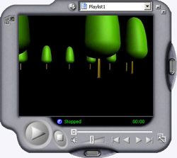
Click the Play button on the Media Player control panel to start the animation. You can also view the animation by dragging the slider. You don't need to use MAX to view a .AVI file. Any computer with Windows installed can be used because the Microsoft Media Player is part of the default installation for the Windows operating system. To play a .AVI file at any time, simply double-click the file icon or right-click and select "Play" from the menu. The AVI file format is particularly useful because it is widely supported by a whole range of graphics software. For example, AVI files can be used as part of a PowerPoint presentation. This is a good way to present AVI animations because you can combine text and other graphics with them.
Adding a Simple Environment
Although we've covered the basics of walkthrough animation, the resulting animation isn't very interesting because we have no environment, only the trees. Let's add a simple ground plane and a sky colour to improve the animation.
 Click the Top viewport to make it current and then use the Zoom tool
 ![]() to zoom out so that the trees form a small group in the middle of the viewport. Click the Create tab on the control panel. Next, click the Geometry button
to zoom out so that the trees form a small group in the middle of the viewport. Click the Create tab on the control panel. Next, click the Geometry button ![]() and then the Cylinder button. Draw a cylinder by selecting a center point in the middle of the tree group and dragging to the edge of the viewport and set a nominal height. Now, using the Parameters rollout, set the Height to -1.0 to ensure that the cylinder is extruded just 1m below the drawing plane. You now have a thin cylinder which will act as a ground plane.
and then the Cylinder button. Draw a cylinder by selecting a center point in the middle of the tree group and dragging to the edge of the viewport and set a nominal height. Now, using the Parameters rollout, set the Height to -1.0 to ensure that the cylinder is extruded just 1m below the drawing plane. You now have a thin cylinder which will act as a ground plane.
You will probably need to set the colour of the circle to something that looks like the ground. To do this, click on the colour square next to the object name (Cylinder01) in the Name and Color rollout. You will be presented with the Object Color palette. Select the required colour and click OK.
To set the sky colour, select Rendering![]() Environment... from the pull-down menu to display the Environment dialogue box. To set the colour, simply click the Color box in the Background section of the dialogue and select an appropriate colour using the Color Selector. Close the Color Selector and the Environment dialogue box.
Environment... from the pull-down menu to display the Environment dialogue box. To set the colour, simply click the Color box in the Background section of the dialogue and select an appropriate colour using the Color Selector. Close the Color Selector and the Environment dialogue box.
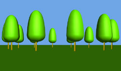 Render your animation as above and you will see that you now have a ground plane and a coloured sky. This gives a much better result than the black background and is very easy to achieve. If you'd like to learn more about environments and how to use environment maps to create realistic looking skies, see the relevant section in the Creating Terrain Objects tutorial.
Donate to CADTutor
If you found this tutorial useful, you might like to consider making a donation. All content on this site is provided free of charge and we hope to keep it that way. However, running a site like CADTutor does cost money and you can help to improve the service and to guarantee its future by donating a small amount. We guess that you probably wouldn't miss $5.00 but it would make all the difference to us.
Local Navigation
Sponsored Links
The Basics
- Dual Dimensions in a Dim…
- UCSICON Options
- "Best of" Basics: Irreg…
- Tool Palette Basics
- Original Dimension Value
- Possible Solutions to th…
- Avoid Using 'Standard' i…
- Shorten the Plot Scales…
- Update the Source File B…
- User Increment Angles fo…
- Drawing Information
- 'Sign Language'
- Rotate with the Copy Opt…
- Use the INSERT Osnap on…
- To or From the Current L…


